Architecture and Modes of Cisco 1841 Router
Understand the external components of Cisco 1841 Router and learn three different modes User EXEC, Previleged and Global Configuration modes.
The front view of the router
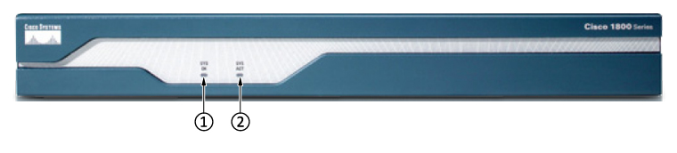
The above is the front view of the Cisco router. We have the logo in the left side and Router model number on the right side which is Cisco 1841. Next, we have two system LED 1 and 2 as follows:
-
System Power (SYS PWR) LED - No power means off and blinking green means that the router is booting.
-
System Activity (SYS ACT) LED - Off means there is no traffic is flowing through the router and blinking green indicated that router is currently moving traffic from one of the port.
The back side of the router
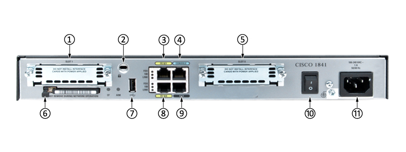
Let us see the different components and their meaning.
-
Slot 1 (WIC, VWIC—data only, or HWIC) - Network Card expansion slot
-
Kensington Security Slot - Secure the router physically from being stolen using the lock.
-
Fast Ethernet ports and LEDs - They have capacity to transmit data at the rate of 100 Mbps. There are three LEDs, FDX (When it is on, it indicated full duplex and when off indicates half duplex operation), 100 (When it is on, it shows 100Mbps and when off indicates 10Mbps) and Link(When it is on, it means that the router is being connected to LAN).
-
Console port - (Management Port) Connecting directly with the computer using console cable for the purpose of configuring the router.
-
Slot 0 (WIC, VWIC—data only, or HWIC) - Network Card expansion slot
-
CompactFlash memory card slot - For inserting the flash memory card. There is light called (CF), which blinks if card is being inserted and being used. On the right of it there is (AM) LED, It is on on if advanced integration module is being installed in the router.
-
USB port - For plugging in an USB drive.
-
Fast Ethernet ports and LEDs
-
Aux port - (Management Port, Backup async port) It works as a backup console port. It can be used for dail-up port for remote router management.
-
On/Off switch - Power on and off the router.
-
Input power connection - Provide the AC power to the Router.
In addition to these, as shown in the image above, there is a ground port between on/off swich and Input power connection which allows the router to be grounded.
Methods of accessing the Router
- In-band access: Used when the router is accessible through network when ip address is configured.
- Out-of-band access: Physical access via console port.
Modes of accessing the Router
| Mode | Prompt | Description |
|---|---|---|
| User EXEC mode | Router> | 1. First Level of Access, 2. Only supports basic commands. |
| Privileged EXEC Mode | Router# | 1. Includes all the commands from User EXEC mode as well, 2. Commands such as view configuration, debug, restart the router, etc. |
| Global Configuration Mode | Router(config)# | 1. Modify the running router configuration, 2. In this mode all the changes are made |
| Router(config-if)# | Interface level within the configuration mode [Ethernet, Serial] (IP address, IPX address) | |
| Router(config-router)# | Routing Engine Level [Rip, ospf] (network, version) | |
| Router(config-line)# | Line level [vty, console] (password, login) |
Commands for navigating to different modes
| Mode | Command |
|---|---|
| Previleged EXEC | enable |
| Global Previleged mode | configure terminal |
Using the built-in help
To access the help we can type ?* (question mark). Using ? sign on terminal will display all the particular available commands at that point in the router.